Thermal Detector Part 3 | Transistor & Buzzer Alarm
Bible Verse – Psalm 32:8 KJV
“I will instruct thee and teach thee in the way which thou shalt go: I will guide thee with mine eye.”
— Psalm 32:8 KJV
1. Introduction
In Video 37, we continue our Thermal Detector series by adding a 2N2222 NPN transistor and an active buzzer to our LM393 comparator circuit.
In Part 1, we used an NTC thermistor and voltage divider to create a voltage that changes with temperature. In Part 2, we added the LM393 comparator. Now we’re using the comparator to control a transistor that switches our buzzer ON and OFF.
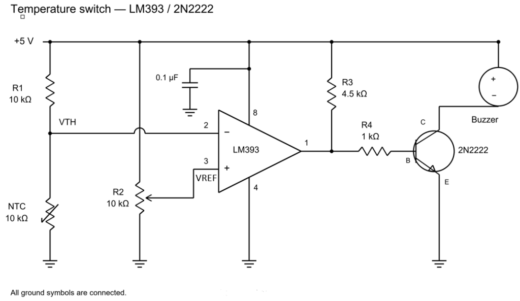
Thermistor → LM393 → 2N2222 → Buzzer
Schematic:
2. Thermistor Voltage Divider
The temperature-sensing portion of the circuit uses a 10 kΩ resistor (R1) and a 10 kΩ NTC thermistor.
The voltage at their junction is called VTH.
Because this is an NTC thermistor:
Temperature increases → Thermistor resistance decreases → VTH decreases
VTH connects to pin 2, the inverting input, of the LM393.
3. Adjustable Reference Voltage
A 10 kΩ potentiometer (R2) is connected between +5 V and ground.
The potentiometer’s wiper provides our adjustable reference voltage:
VREF → LM393 pin 3
For this experiment, VREF was adjusted to approximately:
VREF = 2.39 V
This determines the temperature threshold at which our alarm changes state.
4. LM393 Comparator
At room temperature:
VTH > VREF
The LM393 pulls its pin 1 output LOW, keeping the 2N2222 transistor OFF and the buzzer OFF.
As the thermistor warms, VTH decreases.
When:
VTH < VREF
the LM393 changes state and releases its open-collector output.
5. LM393 Open-Collector Output
The LM393 has an open-collector output. It can actively pull pin 1 LOW, but it cannot actively drive pin 1 HIGH.
That’s why we use:
R3 = 4.5 kΩ pull-up resistor
When the LM393 releases pin 1, R3 allows the output voltage to rise and provides current to the transistor stage.
6. 2N2222 Transistor & Buzzer
The LM393 output connects through:
R4 = 1 kΩ
to the base of our 2N2222 NPN transistor.
The transistor is being used as a low-side switch.
When the transistor turns ON, the current path is:
+5 V → Active Buzzer → 2N2222 Collector → Emitter → Ground
This completes the buzzer circuit and the alarm sounds.
7. 0.1 µF Bypass Capacitor
A 0.1 µF capacitor is connected across the LM393 power supply.
This bypass capacitor helps reduce electrical noise and keeps the local supply voltage at the IC more stable.
You’ll commonly see capacitors like this located near the power pins of integrated circuits.
8. Room-Temperature Measurements – Buzzer OFF
Our measured values at room temperature were:
VCC = 5.02 V
VREF = 2.39 V
VTH = 2.50 V
LM393 VOUT = 0.09 V
2N2222 VB = 0.08 V
2N2222 VC = 5.03 V
Because:
VTH > VREF
the LM393 output is LOW, the 2N2222 is OFF, and the buzzer is OFF.
9. Warming the Thermistor
We then warmed the NTC thermistor.
As its temperature increased, its resistance decreased and VTH dropped.
With the buzzer ON, we measured:
VTH = 2.28 V
Our reference remained approximately:
VREF = 2.39 V
Therefore:
2.28 V < 2.39 V
The threshold had been crossed and the alarm activated.
10. Buzzer-ON Measurements
With the thermistor warmed and the buzzer ON, we measured:
LM393 VOUT = 1.46 V
2N2222 VB = 0.73 V
2N2222 VC = 0.03 V
The approximately 0.73 V base voltage shows that the transistor’s base-emitter junction is forward biased.
The collector dropping to approximately 0.03 V shows that the 2N2222 is operating as a saturated switch.
11. Base-Current Calculation
From our earlier measurements:
VOUT = 1.48 V
VB = 0.73 V
The voltage across our 1 kΩ base resistor R4 is:
VR4 = VOUT − VB
VR4 = 1.48 V − 0.73 V
VR4 = 0.75 V
Using Ohm’s Law:
IB = VR4 / R4
IB = 0.75 V / 1000 Ω
IB = 0.00075 A
Therefore:
IB = 0.75 mA
12. Calculated vs. Measured Base Current
Our calculated base current was:
IB = 0.75 mA
Our actual measured base current was approximately:
IB = 0.72 mA
That’s very close to our calculated value and provides a nice real-world confirmation of our circuit analysis.
13. How the Complete Circuit Works
Putting everything together:
Temperature rises → NTC resistance decreases → VTH decreases → VTH falls below VREF → LM393 releases its output → Base current flows into the 2N2222 → 2N2222 turns ON → Buzzer sounds
We now have a working adjustable temperature alarm!
Whoo Buddy!! ⚡🌡️🔊
My Video Notes:
Thermal Detector Part 3 Transistor & Buzzer Alarm
LAB NOTES:
LAB Measurements
Want more electronics lessons?
For more beginner-friendly electronics lessons, circuit walkthroughs, and hands-on breadboard builds, visit:
https://buildcircuitswithrich.com
Prefer video?
Watch full lessons on the Build Circuits With Rich YouTube Channel.
Back To: Videos