Romans 12:2 (KJV)
2 And be not conformed to this world: but be ye transformed by the renewing of your mind, that ye may prove what is that good, and acceptable, and perfect, will of God.
LM358 Op-Amp | Build a Simple Voltage Amplifier!
Have you ever wondered how an electronic circuit can take a small input voltage and produce a larger voltage at its output?
In this experiment, we’re exploring the LM358 operational amplifier, commonly called an op-amp, and building a simple non-inverting voltage amplifier on a breadboard.
Our goal is to produce approximately twice the input voltage using an LM358 and two resistors to control the voltage gain.
We’ll examine the LM358 datasheet, learn how negative feedback works, calculate our expected output voltages, and then head to the lab to see how closely our actual measurements match our calculations.
Whoo Buddy!! Let’s build a circuit!
Watch the Video:
What Is an Operational Amplifier?
An operational amplifier is an electronic amplifier that responds to the voltage difference between two input terminals.
The LM358 contains two independent operational amplifiers inside a single 8-pin integrated circuit.
Each amplifier has three important terminals:
-
Non-inverting input (+): An increase in voltage here relative to the inverting input tends to increase the output voltage.
-
Inverting input (−): An increase in voltage here relative to the non-inverting input tends to decrease the output voltage.
-
Output: The terminal where we measure the amplified signal.
An op-amp has very high internal voltage gain. Without negative feedback, even a small voltage difference between its inputs can drive the output toward one of its voltage limits.
By using negative feedback, we can create an amplifier with a predictable and controlled voltage gain.
Understanding the LM358 Pinout
The LM358 is a dual operational amplifier, meaning it contains two op-amps in one integrated circuit.
For this experiment, we’re using the first amplifier.
LM358 Pin Functions:
Pin 1: Amplifier 1 Output
Pin 2: Amplifier 1 Inverting Input (−)
Pin 3: Amplifier 1 Non-Inverting Input (+)
Pin 4: Negative Supply (GND in our circuit)
Pin 5: Amplifier 2 Non-Inverting Input (+)
Pin 6: Amplifier 2 Inverting Input (−)
Pin 7: Amplifier 2 Output
Pin 8: Positive Supply (+5 V)
One useful feature of the LM358 is that it can operate from a single positive power supply.
For our experiment, we’re using approximately 5 V.
However, the LM358 has limitations on its input and output voltage ranges. Its output cannot normally reach the full positive supply voltage, so we’ll keep our expected output around 3 V or less.
Manufacturer’s Datasheet: Texas Instruments LM358 Datasheet
Components Used
Here’s what we used to build our voltage amplifier:
-
1 × LM358 dual operational amplifier
-
2 × 10 kΩ resistors for the feedback network
-
1 × 10 kΩ resistor for the unused amplifier
-
1 × 10 kΩ potentiometer
-
1 × 0.1 µF ceramic bypass capacitor
-
1 × Solderless breadboard
-
Jumper wires
-
5 V DC power supply
-
Digital multimeter
Our Non-Inverting Amplifier Circuit:
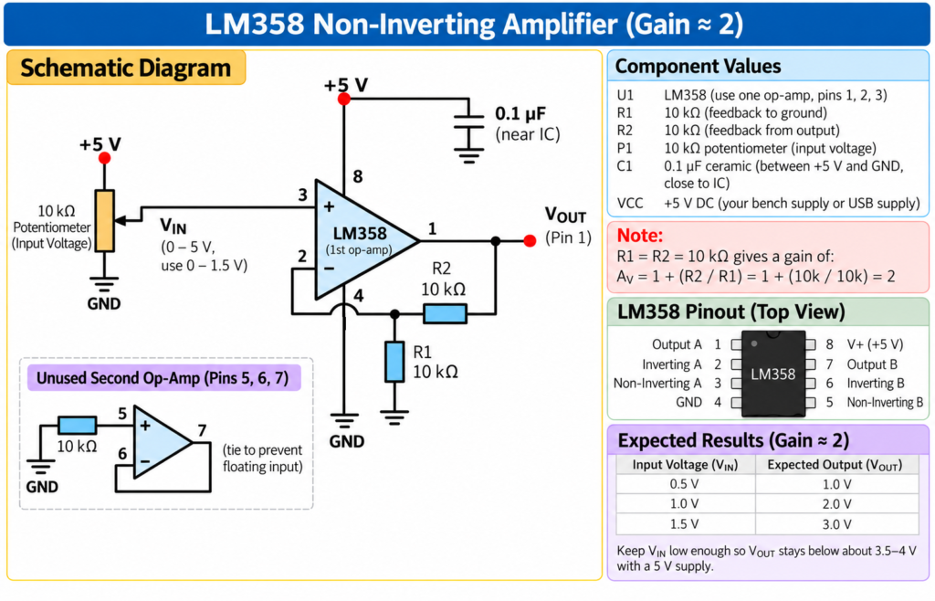 Our circuit uses the LM358 in a non-inverting amplifier configuration.
The 10 kΩ potentiometer connects between +5 V and ground. Its center terminal, called the wiper, provides an adjustable voltage to pin 3, the non-inverting input.
Pin 8 connects to our +5 V supply, while pin 4 connects to ground.
A 0.1 µF ceramic bypass capacitor connects between the supply terminals near the integrated circuit to help reduce unwanted electrical noise.
We measure the amplifier’s output at pin 1.
Two resistors determine our voltage gain:
R1: Connects pin 2, the inverting input, to ground.
R2: Connects pin 1, the output, back to pin 2.
This arrangement creates negative feedback.
Understanding Negative Feedback
Negative feedback is one of the most important concepts in operational amplifier circuits.
As the output voltage increases, a portion of that voltage is fed back through our resistor network to the inverting input.
The LM358 responds by adjusting its output until the voltage at pin 2 is approximately equal to the voltage at pin 3.
These inputs are not physically connected. However, under normal operation with negative feedback, their voltages remain nearly equal.
This condition is sometimes called a virtual short.
Because R1 and R2 are approximately equal, the voltage at pin 2 is approximately half the output voltage.
For example, if we apply 1 V to pin 3, the output needs to rise to approximately 2 V to produce 1 V at pin 2.
That’s how our amplifier produces a voltage gain of approximately two!
Calculating the Voltage Gain
The voltage gain of a non-inverting amplifier is given by:
Av = 1 + (R2 / R1)
Where:
-
Av = Voltage gain
-
R2 = Feedback resistor
-
R1 = Resistor between the inverting input and ground
We’re using two resistors with nominal values of 10 kΩ.
Substituting these values:
Av = 1 + (10,000 / 10,000)
Av = 1 + 1
Av = 2
Our amplifier should therefore produce an output voltage approximately twice the input voltage, provided it remains within its operating limits.
Calculating Gain Using Our Actual Resistor Measurements
Before building the circuit, we measured our resistors using a digital multimeter.
Our actual values were:
R1 = 9.81 kΩ
R2 = 9.76 kΩ
Let’s calculate the gain using these measured values.
Av = 1 + (9.76 / 9.81)
Av = 1 + 0.9949
Av ≈ 1.995
That’s extremely close to our target gain of two!
For an input of exactly 1.00 V:
Vout = Vin × Av
Vout = 1.00 × 1.995
Vout ≈ 1.995 V
That’s what we’ll be looking for when we test our circuit in the lab.
What About the Unused Op-Amp?
The LM358 contains two operational amplifiers, but we’re only using one for this experiment.
Rather than leaving the second amplifier’s inputs floating, we’ve connected it in a defined configuration.
Pin 5, the non-inverting input, connects to ground through a 10 kΩ resistor.
Pin 6, the inverting input, connects directly to pin 7, the output.
This configures the unused amplifier as a voltage follower with its input held near 0 V.
Let’s Head to the Lab!
Well, everyone, we finally made it to the lab!
We assembled our LM358 voltage amplifier on a breadboard and connected our nominal 5 V power supply.
Our actual supply voltage measured:
VCC = 5.04 V
We then adjusted the potentiometer to produce three different input voltages and measured the output using our digital multimeter.
Test 1 — 0.50 V Input
We adjusted the input voltage at pin 3 to approximately 0.50 V.
Our measured output at pin 1 was approximately 1.00 V.
We also measured pin 2 and found approximately 0.50 V, confirming that negative feedback was keeping the two input voltages nearly equal.
Test 2 — 1.00 V Input
Next, we increased the input voltage to 1.00 V.
The output measured approximately 2.00 V!
Pin 2 also measured approximately 1.00 V.
Our amplifier was behaving exactly as predicted by our gain equation.
Test 3 — 1.50 V Input
For our final test, we increased the input voltage to 1.50 V.
The output measured approximately 3.00 V.
Once again, pin 2 measured approximately the same voltage as pin 3.
Lab Measurement Summary:
Test 1 — 0.50 V Input
-
Input Voltage (Pin 3): 0.50 V
-
Inverting Input (Pin 2): 0.50 V
-
Output Voltage (Pin 1): ≈1.00 V
-
Voltage Gain: ≈2
Test 2 — 1.00 V Input
-
Input Voltage (Pin 3): 1.00 V
-
Inverting Input (Pin 2): 1.00 V
-
Output Voltage (Pin 1): ≈2.00 V
-
Voltage Gain: ≈2
Test 3 — 1.50 V Input
-
Input Voltage (Pin 3): 1.50 V
-
Inverting Input (Pin 2): 1.50 V
-
Output Voltage (Pin 1): ≈3.00 V
-
Voltage Gain: ≈2
All three tests demonstrated a voltage gain of approximately two.
Our actual measurements closely matched our theoretical calculations!
All three tests demonstrated a voltage gain of approximately two.
Our actual measurements closely matched our theoretical calculations!
Parts Used in This Experiment
Interested in building this circuit yourself? Here are some of the components and tools used in our experiment.
Affiliate Disclosure: As an Amazon Associate I earn from qualifying purchases. The following links are affiliate links, which means I may earn a small commission at no additional cost to you. Thank you for supporting Build Circuits With Rich!
The dual operational amplifier used in this experiment.
Useful for building feedback networks and experimenting with different voltage gains.
Build and modify electronic circuits without soldering.
Provides an adjustable input voltage for testing the amplifier.
Measure input voltages, output voltages, resistance, and power supply voltage.
Conclusion
In this experiment, we successfully built and tested a simple non-inverting voltage amplifier using the LM358 operational amplifier.
We learned how negative feedback allows us to control voltage gain using just two resistors.
Our calculated gain using the measured resistor values was approximately 1.995, and our lab results confirmed that the amplifier produced approximately twice the input voltage.
We also observed that negative feedback keeps the inverting and non-inverting input voltages nearly equal during normal operation.
This simple circuit demonstrates one of the fundamental building blocks used in analog electronics.
I hope you enjoyed this experiment and learned something new along the way!
If you found this project helpful, please give the video a thumbs up, subscribe to Build Circuits With Rich, and share it with someone who’s interested in learning electronics.
For more beginner-friendly circuits and experiments, visit Build Circuits With Rich.
Thanks for spending time with me, and God bless!
Whoo Buddy!!
My Notes:
Op Amp Video notes
LAB NOTES:
Op Amp lab notes
Want more electronics lessons?
For more beginner-friendly electronics lessons, circuit walkthroughs, and hands-on breadboard builds, visit:
https://buildcircuitswithrich.com
Prefer video?
Watch full lessons on the Build Circuits With Rich YouTube Channel.
Back To: Videos