Thermal Detector Part 2 | LM393 Comparator
Psalm 90:17 — KJV
17 And let the beauty of the LORD our God be upon us: and establish thou the work of our hands upon us; yea, the work of our hands establish thou it.
From Temperature to an ON/OFF Decision
In Part 1 of the Thermal Detector series, we used an NTC thermistor in a voltage divider to produce a voltage that changes with temperature.
In Part 2, we take the next step. We use an LM393 comparator to compare the thermistor voltage with an adjustable reference voltage. When the thermistor voltage crosses our reference voltage, the LM393 changes state and turns on an LED.
What We’re Building
Our circuit has three main sections:
Thermistor Voltage Divider – Senses temperature and produces our thermistor voltage, \(V_{TH}\).
Adjustable Reference – A 10 kΩ potentiometer produces \(V_{REF}\), allowing us to adjust the switching point.
LM393 Comparator – Compares \(V_{TH}\) with \(V_{REF}\) and controls the LED.
Watch the Video
Thermal Detector Part 2 | LM393 Comparator
How the Thermistor Voltage Divider Works
We’re using an NTC thermistor, which stands for Negative Temperature Coefficient.
As the thermistor gets warmer:
Temperature ↑ → Thermistor Resistance ↓ → \(V_{TH}\) ↓
The thermistor voltage is determined by the voltage-divider equation:
\[ V_{TH}=V_{CC}\frac{R_{TH}}{R_1+R_{TH}} \]Where:
- \(V_{CC}\) = supply voltage
- \(R_1\) = fixed resistor
- \(R_{TH}\) = thermistor resistance
- \(V_{TH}\) = thermistor voltage
So we’re taking a change in temperature, turning it into a change in resistance, and then turning that resistance change into a voltage we can use.
Setting the Reference Voltage
A 10 kΩ potentiometer is connected between the 5 V supply and ground.
The center terminal, called the wiper, provides an adjustable voltage called \(V_{REF}\).
Turning the potentiometer raises or lowers \(V_{REF}\). This allows us to adjust the point where the LM393 switches.
LM393 Comparator
The LM393 is a dual comparator, meaning there are two comparators inside the IC. For this project, we’re only using one of them.
LM393 Connections
Connects to our LED output circuit.
Pin 2 – Inverting Input (−)
Connects to our adjustable reference voltage, VREF.
Pin 3 – Non-Inverting Input (+)
Connects to our thermistor voltage, VTH.
Pin 4 – GND
Connects to ground.
Pin 8 – VCC
Connects to our +5 V supply.
The LM393 contains two comparators. The second comparator uses pins 5, 6, and 7, but we’re not using that section in this project.
How the Comparator Works
The LM393 compares our thermistor voltage, \(V_{TH}\), with our adjustable reference voltage, \(V_{REF}\).
At normal temperature:
\[ V_{TH}>V_{REF} \]The output transistor is OFF and the LED is OFF.
As we warm the NTC thermistor, its resistance decreases. This causes \(V_{TH}\) to decrease.
Once:
\[ V_{TH}<V_{REF} \]the LM393 changes state. Its output transistor turns ON and pulls pin 1 LOW.
This completes the current path through the LED and the LED turns ON.
Understanding the Open-Collector Output
The LM393 has what’s called an open-collector output.
Inside the LM393 is an output transistor. When this transistor turns ON, it provides a path toward ground and allows the LM393 to sink current.
When the transistor turns OFF, that path to ground is opened.
An important point is that the LM393 does not actively drive pin 1 HIGH. When its output transistor is OFF, pin 1 is electrically open and the external circuit determines the voltage that appears there.
In our circuit, when the output transistor turns ON, current flows:
+5 V → R2 → LED → LM393 Pin 1 → Ground
The LED turns ON.
When the transistor turns OFF, the current path is broken and the LED turns OFF.
The 0.1 µF Bypass Capacitor
A 0.1 µF capacitor is connected across the power supply near the LM393.
This is called a bypass capacitor, or decoupling capacitor.
It helps filter small voltage spikes and electrical noise on the power supply and helps keep the IC’s supply voltage stable.
It’s good practice to place a small bypass capacitor close to an IC’s power pins.
Components Used
- LM393 dual comparator
- NTC thermistor — approximately 10 kΩ at room temperature
- R1 — approximately 9.9 kΩ
- VR1 — 10 kΩ potentiometer
- R2 — 1.0 kΩ LED current-limiting resistor
- LED
- 0.1 µF bypass capacitor
- Breadboard
- Jumper wires
- 5 V power supply
- Digital multimeter
Lab Measurements
Here are the actual measurements from the circuit demonstrated in the video:
5.03 V
Thermistor Voltage (VTH) at Room Temperature
2.46 V
Reference Voltage (VREF)
2.43 V
LM393 Output LOW
0.15 V
Voltage Across LED
1.87 V
Voltage Across R2
3.01 V
R2 Resistance
1.0 kΩ
Calculating the LED Current
With the LED ON, we measured approximately 3.01 V across R2.
R2 is 1.0 kΩ, so we can use Ohm’s law to calculate the LED current:
\[ I=\frac{V}{R} \]Substituting our measured values:
\[ I_{LED}=\frac{3.01V}{1000\Omega} \]\[ I_{LED}=0.00301A \]Therefore:
\[ \boxed{I_{LED}\approx3.01mA} \]So approximately 3.01 mA is flowing through our LED.
We can also check our voltage measurements:
\[ 3.01V+1.87V+0.15V=5.03V \]That matches our measured 5.03 V supply voltage.
Adjusting the Switching Point
One of the useful features of this circuit is that our switching point is adjustable.
Turning the potentiometer changes \(V_{REF}\).
That means we can adjust the voltage that \(V_{TH}\) must cross before the LM393 changes state.
We’re not directly measuring temperature in degrees with this circuit. Instead, we’re setting a voltage threshold that corresponds to a particular thermistor resistance and therefore a particular temperature.
What We Learned
This project brings together several important electronics concepts:
Thermistor → Senses temperature
Voltage Divider → Converts resistance changes into voltage changes
Potentiometer → Sets an adjustable reference voltage
LM393 Comparator → Makes the ON/OFF decision
LED → Gives us a visual indication
We started with temperature, converted it into a changing voltage, and then used that voltage to control an output.
What’s Next?
In Thermal Detector Part 3, we’ll build on this circuit by adding a buzzer.
Instead of only turning on an LED when we reach our temperature threshold, we’ll use the circuit to give us an audible alarm.
That could be useful for monitoring equipment where we want to hear an alarm if the temperature gets too high.
LM393 Datasheet
When working with an IC, it’s always a good idea to check the manufacturer’s datasheet.
The datasheet allows us to verify important information such as the:
- Pinout
- Power connections
- Electrical characteristics
- Output configuration
LM393 Manufacturer Datasheet:
Add datasheet link here.
Build Circuits With Rich
Learning electronics one circuit at a time.
Whoo Buddy!! ⚡🔧
My Notes:
Video Notes!
LAB NOTES: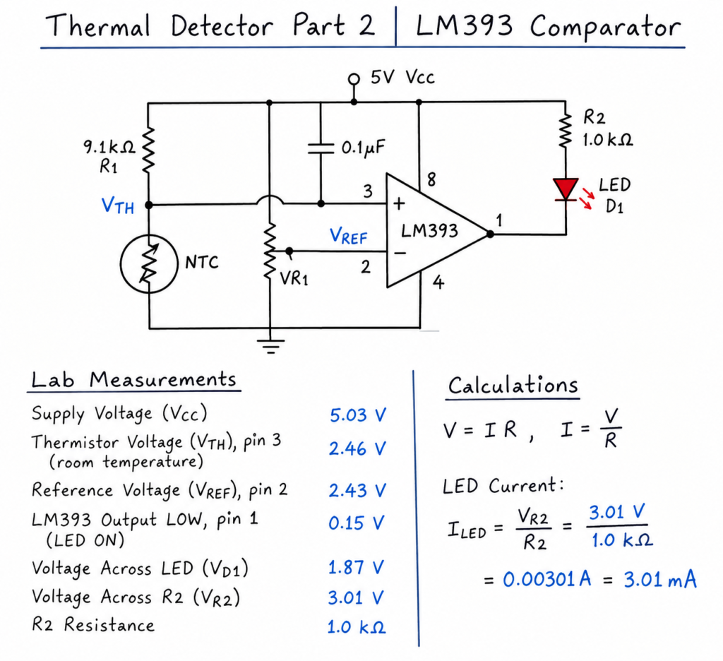
Want more electronics lessons?
For more beginner-friendly electronics lessons, circuit walkthroughs, and hands-on breadboard builds, visit:
https://buildcircuitswithrich.com
Prefer video?
Watch full lessons on the Build Circuits With Rich YouTube Channel.
Back To: Videos