Transistor Logic Basics: Buffer, NOT, AND & NAND (Part 2 of 2)
✝️ Foundation
Before we get into the circuits, I want to share something more important than electronics:
John 3:16 (KJV)
“For God so loved the world, that he gave his only begotten Son, that whosoever believeth in him should not perish, but have everlasting life.”
No matter what we build or learn, this is the most important truth ever known.
In this video, we continue our transistor logic series by building and explaining four very important logic gates:
- OR
- NOR
- XOR
- XNOR
These circuits show how simple transistor stages can be combined to perform real digital logic functions. In this lesson, the gates are built with 2N2222 NPN transistors and powered from 5V, just as shown in the handwritten notes.
Watch the Video Below:
Previously in Part 1
In Part 1, we covered the basic transistor building blocks that make these larger logic circuits possible:
- Inverter
- Buffer
- AND gate
- NAND gate
I reviewed the inverter and buffer truth tables on page 1, and the AND and NAND truth tables on page 2.
Quick recap
Inverter
- Input 0 → Output 1
- Input 1 → Output 0
Buffer
- Input 0 → Output 0
- Input 1 → Output 1
AND gate
- 0 0 → 0
- 0 1 → 0
- 1 0 → 0
- 1 1 → 1
NAND gate
- 0 0 → 1
- 0 1 → 1
- 1 0 → 1
- 1 1 → 0
OR Gate
The OR gate turns the output ON if either input A or input B is ON. Only when both inputs are OFF does the output stay OFF. The handwritten OR-gate page shows a 5V supply, two 1k input resistors, a 470Ω output resistor, an LED at the output, and two 2N2222 NPN transistors.
OR truth table
| A | B | Out |
|---|---|---|
| 0 | 0 | 0 |
| 0 | 1 | 1 |
| 1 | 0 | 1 |
| 1 | 1 | 1 |
OR gate explanation
This gate is useful when you want the output to respond to either one of two inputs. If input A is high, the output turns on. If input B is high, the output also turns on. If both are high, the output is still on.
OR gate parts from the notes
- Supply voltage: 5V
- R1 = 1k
- R2 = 1k
- R3 = 470Ω
- Transistors: 2N2222 NPN
- LED output indicator
NOR Gate
The NOR gate is the opposite of the OR gate. It only turns the output ON when both inputs are OFF. If either input is ON, the output goes OFF. The NOR circuit on the same notes page uses the same general transistor approach and again shows 5V, 1k input resistors, a 470Ω output resistor, LED indicator, and 2N2222 transistors.
NOR truth table
| A | B | Out |
|---|---|---|
| 0 | 0 | 1 |
| 0 | 1 | 0 |
| 1 | 0 | 0 |
| 1 | 1 | 0 |
NOR gate explanation
A NOR gate can be thought of as an OR gate followed by an inverter. In fact, the notes even point out the bubble on the logic symbol as an inversion marker. That small bubble tells us the OR result is being inverted.
NOR gate parts from the notes
- Supply voltage: 5V
- R1 = 1k
- R2 = 1k
- R3 = 470Ω
- Transistors: 2N2222 NPN
- LED output indicator
XOR Gate
The XOR gate stands for Exclusive OR. It turns the output ON only when the two inputs are different. If both inputs are the same, the output is OFF. Your XOR notes show a larger transistor network using 2N2222 devices, a 5V supply, three 1k resistors in the logic network, and a 470Ω resistor for the LED output stage.
XOR truth table
| A | B | Out |
|---|---|---|
| 0 | 0 | 0 |
| 0 | 1 | 1 |
| 1 | 0 | 1 |
| 1 | 1 | 0 |
XOR gate explanation
This is one of the most interesting logic gates because it checks whether the inputs are different.
- If A and B match, output = 0
- If A and B are different, output = 1
That makes XOR very useful in comparison circuits, control logic, and digital arithmetic.
XOR gate parts from the notes
- Supply voltage: 5V
- R1 = 1k
- R2 = 1k
- R3 = 1k
- R4 = 470Ω
- Transistors: 2N2222 NPN
XNOR Gate
The XNOR gate is the opposite of XOR. It turns the output ON when the two inputs are the same. In your notes, the XNOR design uses a multi-transistor arrangement with 2N2222 transistors and includes a mix of 1k, 10k, and 330Ω resistors in the circuit.
XNOR truth table
| A | B | Out |
|---|---|---|
| 0 | 0 | 1 |
| 0 | 1 | 0 |
| 1 | 0 | 0 |
| 1 | 1 | 1 |
XNOR gate explanation
XNOR is often called the “equality” gate because it tells us when two inputs match.
- Same inputs → output ON
- Different inputs → output OFF
This makes XNOR useful for digital comparison and checking whether two signals agree.
XNOR gate parts from the notes
- Supply voltage: 5V
- R1 = 1k
- R2 = 1k
- R3 = 1k
- R4 = 1k
- R5 = 10k
- R6 = 330Ω
- R7 = 1k
- Transistors: 2N2222 NPN
- LED output indicator
High and Low Logic Levels
Also we summarize the idea of digital voltage levels using 0V and 5V:
- 5V = High = 1
- 0V = Low = 0
This is a very important idea in digital electronics. The circuits in this lesson use voltage to represent logic states. A high voltage means logic 1, and a low voltage means logic 0.
From Discrete Transistors to IC Logic
Lastly, in the video, I showed you how transistor logic is used in logic ICs. It shows an example using the 7408, which is a quad 2-input AND gate IC. That is a nice bridge between building logic gates from individual transistors and using pre-made digital chips.
This is one of the coolest things about learning transistor logic from the ground up: once you understand how the logic works at the transistor level, integrated circuits make much more sense.
Why This Lesson Matters
Learning OR, NOR, XOR, and XNOR at the transistor level helps you understand what is happening inside digital systems. These are not just symbols in a truth table — they are real working circuits made from transistors, resistors, and LEDs.
By building these gates yourself, you gain a deeper understanding of:
- digital logic
- transistor switching
- truth tables
- input and output behavior
- how complex digital systems are built from simple stages
Try It Yourself
If you want to follow along, build these circuits on a breadboard and test all four input combinations for each gate. Watch what happens to the LED output and compare your observations to the truth tables above.
Simulations:
OR Gate: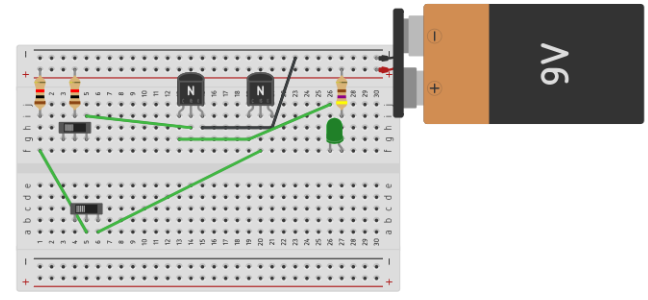
NOR Gate: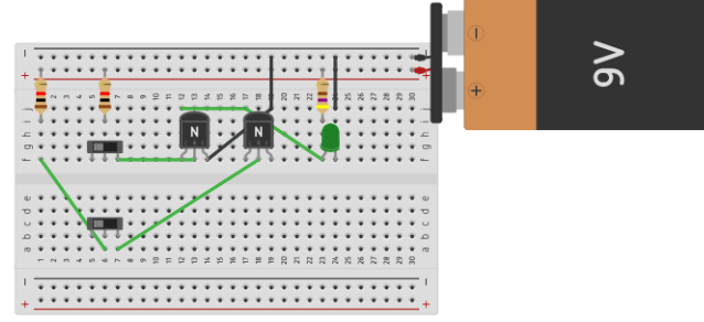
Final Thoughts
Transistor logic is a great way to learn how digital electronics really works. In this lesson, we built four powerful logic gates:
- OR
- NOR
- XOR
- XNOR
Each one performs a different function, but all of them are based on the same core idea: using transistors as switches to control current flow and create logic decisions.
Video Notes:
TransistorLogicNotesPart2
2N2222 Datasheet
Safety Reminder
These circuits use low voltage, but always double-check your wiring before applying power. A small wiring mistake can still cause confusion, incorrect results, or damaged parts.
Want more electronics lessons?
For more beginner-friendly electronics lessons, circuit walkthroughs, and hands-on breadboard builds, visit:
https://buildcircuitswithrich.com
Prefer video?
Watch full lessons on the Build Circuits With Rich YouTube Channel.
Back To: Videos