The Amazing Inductor-Part 1 | What is an Inductor?
📖Foundation:
James 1:5 (KJV)
5 If any of you lack wisdom, let him ask of God, that giveth to all men liberally, and upbraideth not; and it shall be given him.
Introduction
Welcome to The Amazing Inductor series!
In this first lesson, we will answer an important beginner electronics question:
What is an inductor?
In this lesson we’ll explore:
- What an inductor is
- How an inductor creates a magnetic field
- What inductance means
- Air-core, iron-core, and ferrite-core inductors
- The three common inductor schematic symbols
- Why inductance is represented by the letter L
- Why inductance is measured in henrys
- How to build a homemade inductor
- How to turn the homemade inductor into an electromagnet
- How to calculate a safe current-limiting resistor network
What is an Inductor?
An inductor is basically a coil of insulated wire.
Inductors are available in many different sizes and packages. Some are large coils that are easy to see, while others are very small components designed for printed circuit boards.
Even a large spool of motor-winding wire has inductance because the wire is wound into many turns.
When current flows through the coil, it creates a magnetic field around it.
That magnetic field allows the inductor to:
- Store energy
- Act as an electromagnet
- Oppose changes in current
The main idea to remember is:
An inductor is a coil of wire that creates a magnetic field when current flows through it.
Why Use Insulated Magnet Wire?
The wire used to make an inductor must be insulated.
Motor-winding wire, also called magnet wire, has a very thin enamel coating around it. This coating prevents the individual turns of the coil from electrically shorting together.
The coating can be difficult to see because it is extremely thin.
Before connecting the wire to a circuit, the enamel must be carefully scraped away from both ends of the wire.
Do not use bare, uninsulated wire to wind the coil.
If bare wire is wound tightly into a coil, the turns can touch electrically and create a short circuit instead of allowing current to travel through the full length of the coil.
What is Inductance?
Inductance is the property of a coil that opposes changes in current by storing energy in a magnetic field.
When current begins flowing through the coil, the magnetic field builds.
Once the current becomes steady, the magnetic field also becomes steady.
If the current changes, the magnetic field changes with it. This changing magnetic field produces an induced voltage that opposes the change in current.
This effect is especially important in:
- Alternating-current circuits
- Switching power supplies
- Filters
- Transformers
- Motors
- Relays
- Solenoids
Inductance is represented by the letter:
L
The SI unit of inductance is the:
Henry (H)
Inductor Schematic Symbols
Air-Core Inductor
An air-core inductor has no magnetic material inside the coil.
Symbol: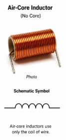
- Radio-frequency circuits
- High-frequency circuits
- Antenna circuits
- Simple demonstrations
Iron-Core Inductor
An iron-core inductor contains a soft-iron or steel core inside the coil.
Symbol:

The iron core concentrates the magnetic field and increases the inductance.
Iron-core inductors are commonly found in:
- Electromagnets
- Power transformers
- Relays
- Solenoids
- Low-frequency power applications
Ferrite-Core Inductor
A ferrite-core inductor contains a magnetic ceramic material called ferrite.
Symbol:
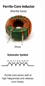
Ferrite helps concentrate the magnetic field while operating efficiently at higher frequencies.
Ferrite-core inductors are commonly found in:
- Switching power supplies
- Electronic filters
- High-frequency circuits
- Radio-frequency circuits
- Modern electronic equipment
How Core Materials Affect an Inductor
An air-core inductor uses only the coil of wire.
Adding an iron or ferrite core changes the magnetic path through the center of the coil.
The core helps concentrate the magnetic field and normally produces more inductance with the same number of turns.
This means that two coils with the same physical size and the same number of turns can have different inductance values if they use different core materials.
Air Core
- No magnetic material
- Lower inductance for the same number of turns
- Works well at high frequencies
- No magnetic core losses
Iron Core
- Produces a stronger magnetic field
- Increases inductance
- Common in power transformers and electromagnets
- Works well at lower frequencies
Ferrite Core
- Magnetic ceramic material
- Increases inductance
- Works well at higher frequencies
- Common in switching power supplies and modern electronics
The main takeaway is that the core material changes the strength and concentration of the magnetic field.
Why is Inductance Represented by L?
Resistance is represented by R, and capacitance is represented by C.
It may seem logical to represent inductance with the letter I, but I is already used to represent electric current.
Inductance is therefore represented by the letter:
L
The use of the letter L is commonly associated with German-Russian physicist Heinrich Lenz, although the exact historical origin of the symbol is not completely certain.
When inductors are labeled in a schematic, they are commonly identified as:
- L1
- L2
- L3
- L4
For example, the first inductor shown in a circuit may be labeled L1.
Heinrich Lenz and Lenz’s Law
Heinrich Lenz lived from 1804 to 1865.
He is best known for Lenz’s Law.
Lenz’s Law states that an induced voltage or current acts in a direction that opposes the change that produced it.
This helps explain why an inductor resists sudden changes in current.
When current through a coil begins increasing, the changing magnetic field induces a voltage that opposes that increase.
When current begins decreasing, the collapsing magnetic field induces a voltage that tries to keep the current flowing.
The negative sign in the inductor-voltage equation represents this opposition:
Vₗ = −L × di/dt
Where:
- Vₗ = voltage across the inductor
- L = inductance in henrys
- di/dt = rate of change of current
- The negative sign represents the opposition described by Lenz’s Law
We will explore Lenz’s Law, Faraday’s Law, and the voltage across an inductor more deeply in future lessons.
Joseph Henry and the Henry
The SI unit of inductance is the henry.
The abbreviation for the henry is:
H
The unit is named in honor of American physicist Joseph Henry, who lived from 1797 to 1878.
Joseph Henry independently discovered electromagnetic induction and made major contributions to:
- Electromagnets
- Electromagnetic induction
- Self-inductance
- Electrical relays
One henry can be expressed as:
1 H = 1 volt-second per ampere
Or:
1 H = 1 V·s/A
Inductors used in electronic circuits are often much smaller than one henry.
Common smaller units include:
- Millihenry: mH
- Microhenry: µH
- Nanohenry: nH
Building a Homemade Inductor
For the lab demonstration, approximately 100 turns of 28 AWG magnet wire were wound into a coil.
A steel nail was placed through the center of the coil.
The nail acts as a magnetic core and helps concentrate the magnetic field.
The inductance of a homemade coil is affected by several factors:
- The number of wire turns
- The diameter of the coil
- The length of the coil
- The spacing between turns
- The material used for the core
- The thickness of the wire
Adding more turns generally increases the inductance and magnetic field.
Adding an iron or steel core also increases the magnetic effect.
Materials Used in the Lab
The homemade electromagnet demonstration used:
- 28 AWG enamel-coated magnet wire
- Approximately 100 turns of wire
- A steel nail
- A 9-volt battery
- A battery connector
- Five 22-ohm, one-quarter-watt resistors
- A breadboard
- Jumper wires
- A multimeter
- A small steel tack or similar metal object
Preparing the Magnet Wire
The magnet wire has a thin enamel coating that must be removed from the ends before making an electrical connection.
To prepare the wire:
- Leave several inches of wire at each end of the coil.
- Carefully scrape the enamel coating from each end.
- Continue scraping until the copper surface is visible.
- Use a multimeter to confirm continuity through the coil.
- Attach alligator clips or jumper wires if necessary.
If the enamel is not completely removed, the meter may show an open circuit and current will not flow through the coil.
Measuring the Homemade Coil
Before powering the coil, its DC resistance was measured with a multimeter.
The measured resistance varied from approximately:
1.6 to 1.8 ohms
For the circuit calculations, the coil resistance was rounded to:
Rₗ = 2 Ω
This is a very low resistance.
Connecting the coil directly across a 9-volt battery would allow excessive current to flow.
A current-limiting resistor network is therefore required.
Why a Current-Limiting Resistor is Needed
Using Ohm’s Law, a 2-ohm coil connected directly across an ideal 9-volt source would attempt to draw:
I = V ÷ R
I = 9 V ÷ 2 Ω
I = 4.5 A
A small rectangular 9-volt battery cannot properly supply 4.5 amps. Its voltage would collapse, the battery could become hot, and the coil or connecting wires could also overheat.
The series resistance limits the current to a much safer value.
For this demonstration, the target current was selected as:
80 mA
Choosing the Current
The desired current is:
I = 80 mA
Convert milliamps to amps:
80 mA = 0.080 A
This current should produce a visible magnetic effect while reducing stress on the battery and circuit components.
Calculating the Total Resistance
Use Ohm’s Law:
V = I × R
Rearrange the equation to solve for resistance:
Rₜ = V ÷ I
Insert the known values:
Rₜ = 9 V ÷ 0.080 A
Rₜ = 112.5 Ω
The entire circuit should therefore have approximately 112.5 ohms of resistance to limit the current to 80 milliamps.
Calculating the Required Series Resistance
The total resistance includes both the current-limiting resistance and the resistance of the coil.
Rₜ = Rₛ + Rₗ
Where:
- Rₜ = total circuit resistance
- Rₛ = series current-limiting resistance
- Rₗ = coil resistance
Rearrange the equation:
Rₛ = Rₜ − Rₗ
Insert the known values:
Rₛ = 112.5 Ω − 2 Ω
Rₛ = 110.5 Ω
We need approximately 110.5 ohms of series resistance.
Using Five 22-Ohm Resistors
The available resistors were:
22 Ω, ¼ W
Resistors connected in series add together.
Rₛ = R1 + R2 + R3 + R4 + R5
Using five 22-ohm resistors:
Rₛ = 22 Ω + 22 Ω + 22 Ω + 22 Ω + 22 Ω
Rₛ = 110 Ω
Add the 2-ohm coil resistance:
Rₜ = 110 Ω + 2 Ω
Rₜ = 112 Ω
This is very close to the calculated target of 112.5 ohms.
Calculating the Actual Current
Use Ohm’s Law:
I = V ÷ R
I = 9 V ÷ 112 Ω
I = 0.0804 A
Convert amps to milliamps:
I = 80.4 mA
The actual calculated current is approximately:
80 mA
Checking the Total Resistor Power
The total power dissipated by the five-resistor network can be calculated using:
P = I² × R
Using the 110-ohm resistor network:
P = (0.0804 A)² × 110 Ω
P ≈ 0.711 W
One quarter-watt resistor could not safely dissipate this entire amount of power.
That is why the resistance was divided among five separate resistors.
Checking the Power in Each Resistor
Each resistor has a value of 22 ohms.
Use:
P = I² × R
Insert the values:
P = (0.0804 A)² × 22 Ω
P ≈ 0.142 W
Each resistor dissipates approximately:
0.142 W
The resistor rating is:
0.25 W
Because:
0.142 W < 0.25 W
Each resistor is operating below its rated power.
Using five resistors spreads the total heat between them.
Circuit Arrangement
The components are connected in series:
9 V Battery → 22 Ω → 22 Ω → 22 Ω → 22 Ω → 22 Ω → Homemade Coil → Battery Negative
Because all the parts are connected in series, the same current flows through:
- Each resistor
- The homemade coil
- The battery
The individual resistor values add together to form the total series resistance.
Testing the Electromagnet
After the circuit was connected to the 9-volt battery, current flowed through the homemade coil.
The current created a magnetic field around the coil.
The steel nail concentrated the magnetic field and became an electromagnet.
The electromagnet was able to attract and lift a small steel object.
The magnetic effect was not extremely strong, but it successfully demonstrated that:
- Current creates a magnetic field
- A coil strengthens the magnetic effect
- A steel core concentrates the field
- A homemade inductor can act as an electromagnet
The electromagnet could be made stronger by:
- Adding more turns
- Increasing current safely
- Improving the core material
- Winding the coil more tightly
- Reducing gaps between the coil and core
Safety Reminder
This experiment uses a small 9-volt battery and a calculated current-limiting resistor network.
Never connect a homemade coil directly to a household wall outlet.
Household AC voltage can cause serious injury or death.
Also remember:
- Do not connect a low-resistance coil directly across a battery.
- Use a properly calculated current-limiting resistor.
- Verify resistor wattage ratings.
- Make the battery connection only briefly.
- Disconnect the circuit if the battery becomes warm.
- Disconnect the circuit if the resistors become warm.
- Disconnect the circuit if the wire becomes warm.
- Double-check the breadboard connections before applying power.
- Ask for experienced help whenever you are unsure.
Key Takeaways
- An inductor is a coil of insulated wire.
- Current flowing through a coil creates a magnetic field.
- An inductor stores energy in its magnetic field.
- Inductors oppose changes in current.
- Inductance is represented by the letter L.
- Inductance is measured in henrys, abbreviated H.
- Air, iron, and ferrite cores affect the inductor differently.
- An iron or steel nail can help concentrate the magnetic field.
- Heinrich Lenz is known for Lenz’s Law.
- Joseph Henry made important contributions to electromagnetism.
- A low-resistance coil requires current limiting.
- Five 22-ohm resistors produced approximately 110 ohms.
- The completed circuit carried approximately 80 milliamps.
- The homemade coil and nail successfully acted as an electromagnet.
Conclusion
In this lesson, we learned that an inductor is much more than a simple coil of wire.
When current flows through the coil, it creates a magnetic field. That field stores energy and causes the inductor to oppose changes in current.
We also explored:
- The three common inductor schematic symbols
- Air, iron, and ferrite cores
- Why inductance uses the letter L
- Why inductance is measured in henrys
- Joseph Henry
- Heinrich Lenz
- How to build a homemade coil
- How to calculate a safe current-limiting resistor network
- How to create a simple electromagnet
This gives us the foundation we need to continue learning about magnetic fields, Faraday’s Law, Lenz’s Law, self-inductance, RL circuits, and transformers.
We’ll continue building our understanding one baby step at a time!
Whoo Buddy!
My Notes:
Video Notes
Want more electronics lessons?
For more beginner-friendly electronics lessons, circuit walkthroughs, and hands-on breadboard builds, visit:
https://buildcircuitswithrich.com
Prefer video?
Watch full lessons on the Build Circuits With Rich YouTube Channel.
Back To: Videos