Psalm 118:23–24 (KJV)
23 This is the LORD’S doing; it is marvellous in our eyes.
24 This is the day which the LORD hath made; we will rejoice and be glad in it.
Build A Night Light Circuit
Build a Night-Light Circuit with a Photoresistor & 2N2222:
Try building the circuit yourself and experiment with different resistor values or different amounts of light hitting the photoresistor.
And most importantly — have fun building circuits!
Whoo Buddy! ⚡
Build Circuits With Rich
buildcircuitswithrich.com
In this lesson, we’ll build a simple automatic night-light circuit using a photoresistor and a 2N2222 NPN transistor.
The circuit automatically turns the LED:
OFF when the light is bright
ON when it gets dark
Along the way, we’ll look at how a photoresistor works, use a voltage divider to control the transistor, calculate the LED current-limiting resistor, and compare our calculated values with real measurements from the breadboard circuit.
How a Photoresistor Works
A photoresistor, also called an LDR (Light-Dependent Resistor), changes resistance depending on the amount of light striking its surface.
In bright light, its resistance decreases.
In darkness, its resistance increases.
The photoresistor used in this project measured approximately:
| Lighting Condition | Photoresistor Resistance |
|---|---|
| Bright light | ≈ 1 kΩ |
| Covered / dark | ≈ 100 kΩ or more |
The exact resistance depends on the photoresistor and the amount of light reaching it.
A photoresistor is also non-polarized, so it can be installed in either direction.
Circuit Components
For this project we used:
- 5 V power supply — measured at 5.04 V
- 2N2222 NPN transistor
- Photoresistor / LDR
- R1 = 10 kΩ
- R2 = 330 Ω
- Red LED
- Breadboard
- Jumper wires
- Multimeter
How the Circuit Works
R1 and the photoresistor form a voltage divider.
The junction between R1 and the photoresistor connects directly to the base of the 2N2222 transistor.
When the photoresistor is exposed to bright light, its resistance becomes low. This pulls the transistor base voltage toward ground.
The transistor turns OFF, stopping current through the LED.
When the light level decreases, the resistance of the photoresistor increases. The base voltage rises until the transistor begins conducting.
The transistor then turns ON, allowing current to flow:
+5 V → R2 → LED → Q1 Collector → Q1 Emitter → Ground
The LED turns on.
Calculating the LED Resistor R2
We chose an LED current of approximately:
ILED = 10 mA
Our measured supply voltage was:
VCC = 5.04 V
For the initial design we estimated:
VLED ≈ 2.0 V
VCE(sat) ≈ 0.2 V
Using Kirchhoff’s Voltage Law:
VCC − VR2 − VLED − VCE(sat) = 0
Solve for the voltage across R2:
VR2 = VCC − VLED − VCE(sat)
Substitute the values:
VR2 = 5.04 − 2.0 − 0.2
VR2 = 2.84 V
Now use Ohm’s Law:
R2 = VR2 / ILED
R2 = 2.84 V / 0.010 A
R2 = 284 Ω
The closest resistor value we had available was:
R2 = 330 Ω
The slightly larger resistor also reduces the LED current somewhat below our 10 mA design target.
Daylight — LED OFF
In bright light, the photoresistor measured approximately:
Rphoto = 1 kΩ
The voltage divider equation is:
VB = VCC × Rphoto / (R1 + Rphoto)
Substitute the values:
VB = 5.04 × 1 kΩ / (10 kΩ + 1 kΩ)
VB = 5.04 × 1 / 11
VB ≈ 0.46 V
The actual measured base voltage was approximately:
VB ≈ 0.43–0.45 V
That voltage is too low to significantly forward-bias the transistor’s base-emitter junction, so the transistor remains essentially OFF.
With the transistor off:
Collector current ≈ 0 mA
LED = OFF
Dark — LED ON
When the photoresistor was covered, its resistance increased to approximately:
Rphoto = 100 kΩ
Using the same divider equation:
VB = 5.04 × 100 kΩ / (10 kΩ + 100 kΩ)
VB ≈ 4.58 V
However, this value represents the voltage divider by itself — unloaded.
Once the transistor is connected and its base-emitter junction becomes forward biased, the transistor draws current from the divider.
That loads the voltage divider, so the simple unloaded-divider equation no longer predicts the actual base voltage.
The measured base voltage with the transistor conducting was approximately:
VB ≈ 0.69–0.70 V
That is right around what we would expect for a conducting silicon base-emitter junction.
Loaded vs. Unloaded Voltage Divider
We also disconnected the transistor from the divider and measured the divider by itself.
With the divider unloaded, the dark-state voltage measured approximately:
4.57 V
Our calculated value was:
4.58 V
That is extremely close.
When the transistor was connected and conducting, the measured base voltage dropped to approximately:
0.69 V
This demonstrates the difference between a loaded and unloaded voltage divider.
| Voltage Divider Condition | Voltage |
|---|---|
| Calculated unloaded | 4.58 V |
| Measured unloaded | 4.57 V |
| Measured with transistor conducting | ≈ 0.69–0.70 V |
LED and Transistor Measurements
With the LED turned on, the transistor collector voltage dropped to approximately:
VC ≈ 0.02 V
Because the emitter is connected directly to ground:
VCE ≈ 0.02 V
That means the transistor is operating very close to an ideal closed switch.
The LED anode measured approximately:
1.98 V
The cathode is connected to the transistor collector:
VC ≈ 0.02 V
Therefore:
VLED = 1.98 − 0.02
VLED ≈ 1.96 V
That is very close to the 2.0 V value we originally used when designing R2.
Calculating the Actual LED Current
With the LED on:
VCC = 5.04 V
LED anode voltage ≈ 1.98 V
Therefore the voltage across R2 is approximately:
VR2 = 5.04 − 1.98
VR2 = 3.06 V
Using Ohm’s Law:
I = VR2 / R2
I = 3.06 / 330
I ≈ 0.00927 A
or:
I ≈ 9.27 mA
Our actual measured current was approximately:
9.35–9.36 mA
That is extremely close to the calculated value and also very close to our original 10 mA design target.
Calculated vs. Measured Results
| Measurement | Daylight — LED OFF | Dark — LED ON |
|---|---|---|
| VCC | 5.04 V | 5.04 V |
| Photoresistor | ≈ 1 kΩ | ≈ 100 kΩ |
| Base voltage VB | ≈ 0.43–0.45 V | ≈ 0.69–0.70 V |
| Collector voltage VC | ≈ 3.5 V measured | ≈ 0.02 V |
| Emitter voltage VE | 0 V | 0 V |
| LED anode voltage | ≈ 5.04 V | ≈ 1.98 V |
| LED cathode voltage | ≈ 3.5 V measured | ≈ 0.02 V |
| LED voltage | LED OFF | ≈ 1.95–1.96 V |
| Voltage across R2 | ≈ 0 V | ≈ 3.05–3.06 V |
| Collector / LED current | ≈ 0 mA | ≈ 9.35 mA |
| LED state | OFF | ON |
What We Learned
This little circuit demonstrates several important electronics concepts at the same time:
Photoresistors can sense changes in light.
A voltage divider can convert a changing resistance into a changing voltage.
A 2N2222 transistor can be used as an electronic switch.
A resistor is used to limit LED current.
Kirchhoff’s Voltage Law and Ohm’s Law can be used to design the circuit before building it.
And finally, real measurements can be compared with our calculated values to see how well our design works.
The measurements in this project came very close to what we predicted — especially the LED current, where we calculated approximately 9.27 mA and measured approximately 9.35 mA.
My Notes:
Video Notes
LAB NOTES: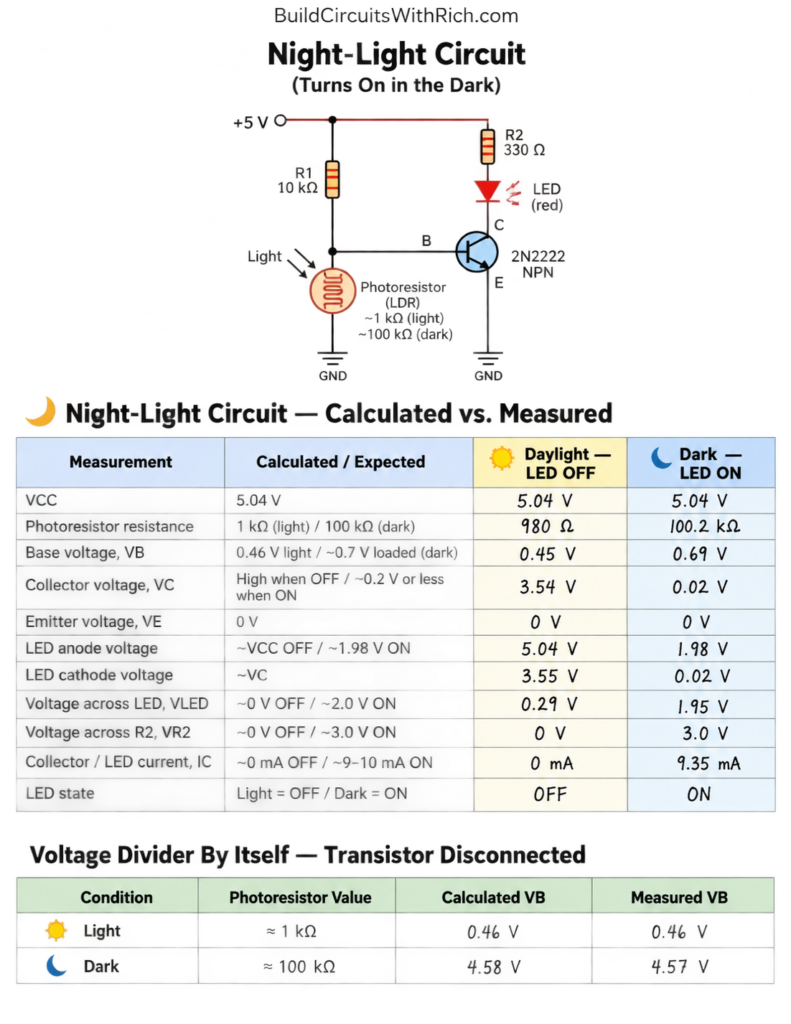
Want more electronics lessons?
For more beginner-friendly electronics lessons, circuit walkthroughs, and hands-on breadboard builds, visit:
https://buildcircuitswithrich.com
Prefer video?
Watch full lessons on the Build Circuits With Rich YouTube Channel.
Back To: Videos