Transistor Logic Basics: Buffer, NOT, AND & NAND (Part 1 of 2)
In This Lesson
In this lesson, we explore how transistors can be used to create logic circuits.
We will cover:
- NPN transistor basics (2N2222)
- Buffer circuit
- Inverter (NOT gate)
- AND gate
- NAND gate
- Truth tables
- Basic resistor calculations
Watch Video:
🔌 NPN Transistor Basics
We are using an NPN transistor (2N2222).
It has three terminals:
- Base (B)
- Collector (C)
- Emitter (E)
👉 A transistor acts like a switch:
- No base current → OFF
- Base current present → ON
⚡ Transistor as a Switch
There are three main operating regions:
- Cutoff → OFF
- Active → Partially ON
- Saturation → Fully ON (used for switching)
👉 For digital logic, we mainly use:
- OFF (cutoff)
- ON (saturation)
🔁 Buffer Circuit
A buffer simply copies the input to the output.
Truth Table
| Input | Output |
|---|---|
| 0 | 0 |
| 1 | 1 |
👉 Output follows input exactly.
Simulation:![]()
💡 LED Resistor Calculation
Using:
- Supply = 5V
- Transistor drop ≈ 0.2V
- LED drop ≈ 2V
Voltage across resistor:
5V − 0.2V − 2V = 2.8V
If desired current = 10mA:
R = V / I = 2.8V / 0.01A = 280Ω
👉 Practical value used:
- 470Ω
💡 Base Resistor Calculation
- V_BE ≈ 0.7V
- Voltage across resistor = 5V − 0.7V = 4.3V
Assume:
- I_C ≈ 10mA
- β ≈ 10 (safe estimate)
Then:
I_B = I_C / β = 10mA / 10 = 1mA
R = V / I = 4.3V / 1mA = 4.3kΩ
👉 Practical value used:
- 4.7kΩ
🔄 Inverter (NOT Gate)
The inverter flips the input.
Truth Table
| Input | Output |
|---|---|
| 0 | 1 |
| 1 | 0 |
👉 If input is LOW → output is HIGH
👉 If input is HIGH → output is LOW
Simulation: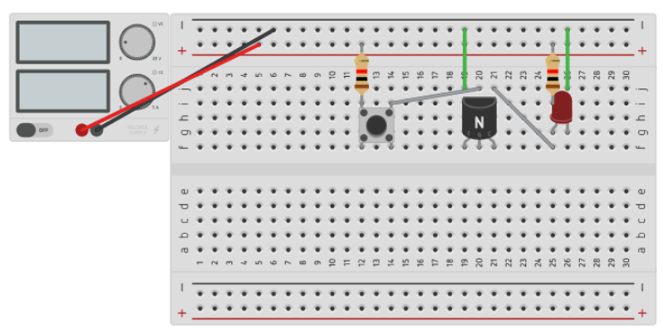
AND Gate (Using Transistors)
Two transistors are placed in series.
👉 Both must be ON for current to flow.
Truth Table
| A | B | Output |
|---|---|---|
| 0 | 0 | 0 |
| 0 | 1 | 0 |
| 1 | 0 | 0 |
| 1 | 1 | 1 |
👉 Output is HIGH only when BOTH inputs are HIGH.
Simulation: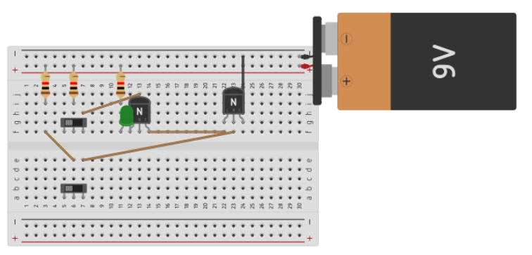
NAND Gate
NAND is the inverse of AND.
👉 Output is LOW only when BOTH inputs are HIGH.
Truth Table
| A | B | Output |
|---|---|---|
| 0 | 0 | 1 |
| 0 | 1 | 1 |
| 1 | 0 | 1 |
| 1 | 1 | 0 |
👉 NAND = NOT(AND)
Simulation: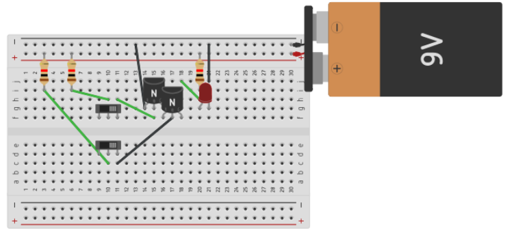
🧠 Key Takeaway
By combining transistors as switches, we can build:
- Basic logic functions
- Complex digital systems
👉 This is the foundation of digital electronics.
Video Notes:
Transistor-Logic-Part1-Video-Notes
2N2222 Datasheet
📖 Closing Verse (KJV)
23 The Lord is my shepherd; I shall not want.
2 He maketh me to lie down in green pastures: he leadeth me beside the still waters.
3 He restoreth my soul: he leadeth me in the paths of righteousness for his name’s sake.
4 Yea, though I walk through the valley of the shadow of death, I will fear no evil: for thou art with me; thy rod and thy staff they comfort me.
5 Thou preparest a table before me in the presence of mine enemies: thou anointest my head with oil; my cup runneth over.
6 Surely goodness and mercy shall follow me all the days of my life: and I will dwell in the house of the Lord for ever.
Prefer video?
Watch full lessons on the Build Circuits With Rich YouTube Channel.
Back To: Videos