Decimal-to-Binary Encoder Using Only Diodes
Build Circuits With Rich
In this video we build a decimal-to-binary encoder using only diodes. This circuit demonstrates how simple components can perform digital logic functions without using integrated circuits.
By arranging diodes in a specific pattern, a selected decimal input is converted into a binary output.
What You Will Learn
In this video you will learn:
-
How decimal numbers are encoded into binary
-
How diode networks can implement logic
-
How binary output lines represent weighted bits
-
How to build digital circuits on a breadboard
Watch the Video:
Try the Circuit Yourself
Interactive simulation: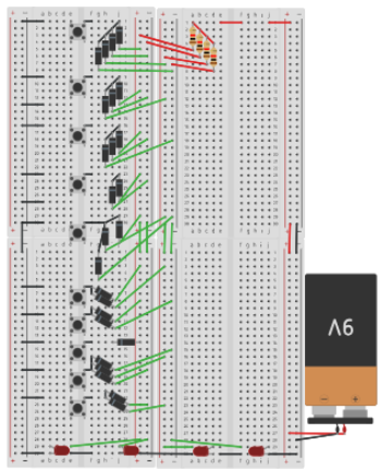
Understanding the Encoder
A decimal-to-binary encoder converts one of ten decimal inputs (0–9) into a binary output.
In this project we use the 8421 binary system, where each output line represents a binary weight:
-
8 (2³)
-
4 (2²)
-
2 (2¹)
-
1 (2⁰)
These outputs are displayed using LED indicators.
When an LED is:
-
ON → Binary 1
-
OFF → Binary 0
This allows us to directly see the binary number produced by the encoder.
Important Rule
Only one decimal input switch should be closed at a time.
If multiple inputs are activated, the encoder output will not represent a valid decimal-to-binary conversion.
Decimal to Binary Truth Table
| Decimal | Binary |
|---|---|
| 0 | 0000 |
| 1 | 0001 |
| 2 | 0010 |
| 3 | 0011 |
| 4 | 0100 |
| 5 | 0101 |
| 6 | 0110 |
| 7 | 0111 |
| 8 | 1000 |
| 9 | 1001 |
This truth table shows the binary output produced when each decimal input is selected.
How Diode Logic Makes This Work
Diodes allow current to flow in only one direction.
By connecting diodes between the decimal inputs and the binary output lines, the circuit routes voltage to the correct output lines for each number.
This technique is called diode logic.
It is one of the earliest methods used to build digital logic circuits before modern integrated circuits were common.
Circuit Components
This project uses simple components:
-
Diodes
-
Resistors (470Ω pull-ups)
-
LEDs
-
Breadboard
-
Pushbutton switches
-
5V power supply
Inspiration
This circuit concept is inspired by the work of Forrest M. Mims III and the classic Engineer’s Mini Notebook series.
My Handwritten Notes
You can download the notes used in this lesson here:
Download the notes:
Rich’s Video Notes
Scripture for the Lesson
Romans 15:13 (KJV)
“Now the God of hope fill you with all joy and peace in believing, that ye may abound in hope, through the power of the Holy Ghost.”
Build Circuits With Rich
This channel and website focus on hands-on electronics learning, where we build real circuits and explore how they work.
Prefer video?
Watch full lessons on the Build Circuits With Rich YouTube Channel.
Back To: Videos