4N35 Opto-Coupler
Build Circuits With Rich
Learn how to control one circuit with another using light instead of a direct electrical connection. In this lesson, we use the 4N35 opto-coupler to show how a 3.3V input can safely control a 5V output while keeping the two sides electrically isolated.
Watch the Lesson
What Is an Opto-Coupler?
An opto-coupler, also called an opto-isolator, is a device that transfers a signal by using light inside the component.
Inside the 4N35 are two main parts:
- An internal LED on the input side
- An internal phototransistor on the output side
When the LED turns on, it shines light onto the phototransistor. The phototransistor then turns on, allowing the output circuit to respond.
The important part is this:
The input side and output side are electrically isolated.
That means the signal is transferred without a direct electrical connection between the two circuits.
Quick Review: Transistor Switching
Before looking at the opto-coupler itself, it helps to remember how an NPN transistor behaves in three regions shown in your notes: cutoff, active, and saturation.
Cutoff
The base-emitter voltage is below about 0.7V, so the transistor is OFF. It acts like an open switch and no collector current flows.
Active Region
The transistor can amplify. This is the region used for amplifier operation.
Saturation
The transistor is driven fully ON. It acts like a closed switch, and the collector-emitter voltage is very low, about 0.2V.
In this lesson, the output transistor inside the opto-coupler is mainly being used as a switch.
4N35 Pin Basics
Your notes show the 4N35 with these key pins: input LED on pins 1 and 2, and output transistor collector and emitter on pins 5 and 4.
Input side
- Pin 1: Anode
- Pin 2: Cathode
- Pin 3: Not Connected
Output side
- Pin 5: Collector
- Pin 4: Emitter
- Pin 6: Base
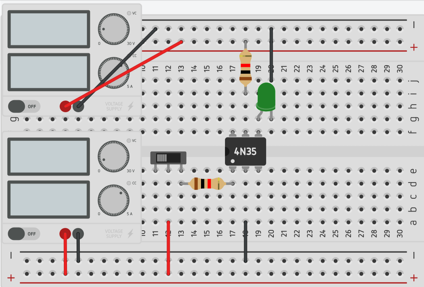
In this lesson, the input side uses 3.3V and the output side uses 5V.
Input Side Circuit (3.3V)
The internal LED in the 4N35 has a forward voltage of about 1.2V in your notes.
To safely limit the input current, use a resistor on the input side.
Input resistor calculation
Choose about 5 mA for reliable operation.
R1 = (Vin – 1.2V) / I
Using 3.3V input:
R1 = (3.3V – 1.2V) / 5 mA
R1 = 2.1V / 0.005A
R1 = 420 ohms
Nearest common value:
Use 470 ohms
Output Side Circuit (5V)
Your notes show a 5V output side with an LED load and about 0.2V across the output transistor in saturation, with the LED around 2.1V.
Output resistor calculation
Given:
- Vcc = 5V
- LED drop = 2.1V
- Transistor saturation voltage = 0.2V
- Desired current = 3 mA
R2 = (5V – 2.1V – 0.2V) / 3 mA
R2 = 2.7V / 0.003A
R2 = 900 ohms
Nearest common value:
Use 1k ohm
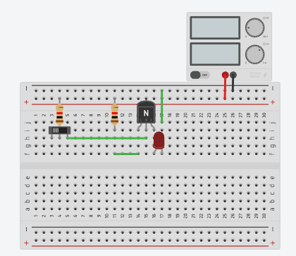
How the Circuit Works
When the input is OFF
No current flows through the internal LED. No light is produced. The phototransistor stays OFF, so the output side remains OFF.
When the input is ON
Current flows through the internal LED. Light is produced inside the 4N35. The phototransistor turns ON, current flows on the output side, and the output LED lights up.
This is a great real-world example of cutoff and saturation used in switching.
Why Opto-Couplers Matter
Opto-couplers let one circuit control another circuit while keeping them electrically isolated.
Benefits
- Protect sensitive electronics
- Allow different voltage levels to work together
- Reduce electrical noise
- Useful in microcontrollers, switching circuits, and interface circuits
Key Takeaways
- An opto-coupler transfers a signal using light
- The 4N35 contains an LED and a phototransistor
- A 470Ω resistor works well on the 3.3V input side
- A 1kΩ resistor works well on the 5V output side
- The transistor operates like a switch in cutoff and saturation
- Isolation is one of the biggest reasons to use an opto-coupler
Components Used
- 4N35 opto-coupler
- 470Ω resistor
- 1kΩ resistor
- LED
- 3.3V source
- 5V source
- Breadboard
- Jumper wires
Try out the transistor as a switch simulation:
Try out the Opto-Coupler simulation:
Final Thoughts
Opto-couplers are a simple but powerful way to connect circuits safely. Once you understand the internal LED and transistor, the whole device becomes much easier to understand.
Video Notes:
Bible Verse
Isaiah 41:10 (KJV)
Fear thou not; for I am with thee: be not dismayed; for I am thy God: I will strengthen thee; yea, I will help thee; yea, I will uphold thee with the right hand of my righteousness.
Prefer video?
Watch full lessons on the Build Circuits With Rich YouTube Channel.
Back To: Videos